Paper Qubits
A quantum computer, drawn in pencil and simulated exactly. Add gates, watch the arrows and clocks, then measure and compare what you get with the prediction.
Control the chip
From the chip to the notation
| On the chip | In the notation |
|---|---|
| Left alone in the fridge, the circuit settles into its lowest energy level | |0⟩ |
| The next energy level up, 5.00 GHz higher | |1⟩ |
| A microwave pulse at exactly 5.00 GHz, length t | rotation Ry(θ), θ ∝ t |
| π/2 pulse: half of a full flip | |0⟩ → (|0⟩+|1⟩)/√2 = |+⟩ the H of lesson 1 |
| π pulse: a full flip | X: |0⟩ → |1⟩ |
| One readout: the dot lands left or right of the line | measurement → 0 or 1 |
| Share of dots on the right, over many shots | P(1) = |amplitude of |1⟩|² |
| Waiting: energy leaks out (T1 = 60 µs), phase blurs (T2 = 45 µs) | the arrow shrinks: noise |
Control the chip
From the chip to the notation
| On the chip | In the notation |
|---|---|
| Two aluminium crosses: Q0 at 5.00 GHz, Q1 at 5.30 GHz | q0, q1; joint |q1 q0⟩ |
| A 26 ns pulse on each drive line, D0 and D1 | Ry(π/2) on each ≈ H |
| A 60 ns flux pulse on the coupler between the crosses | CZ: |11⟩ gets phase φ (ideal φ = 180°, a − sign) |
| A −π/2 pulse on D1 after the coupler | all together: CNOT q0→q1 (lesson 3) |
| Both arrows shrink while the coupler pulse plays | entangled: no state of its own |
| Two resonators on one feedline, read at the same time | measure both → 00…11 |
| Both dots land on the same side far more often than chance | correlation: P(00) + P(11) |
| Coupler pulse too weak, too strong, or off | φ ≠ 180°: partly or not entangled |
Pick a gate
What the compiler makes of it
RZ is free: the control software shifts the phase of the later pulses instead of playing anything. SX, X and CZ are real pulses. The native set here matches IBM-style chips; durations are typical, not one chip's specs.
Circuit
In electronics
On the chip
Pulse schedule: the gate as the chip receives it
A flip-flop and a qubit, side by side
| Logic gate / flip-flop | Quantum gate / qubit | |
|---|---|---|
| A bit is | a voltage on a node (0 V or ~0.8 V), held by feedback | which energy level a circuit is in, or any arrow in between |
| A gate is | transistors the data flows through, onto a new wire | a timed pulse sent to a qubit that stays put |
| A circuit is | wiring, fixed in silicon | a program, compiled to a pulse schedule and played in time |
| Speed | picoseconds per gate, GHz clocks | ~36 ns per pulse, ~70 ns per coupler gate, ~1 µs to read |
| Memory lasts | as long as the power is on | ~100 µs, then the qubit drifts back to |0⟩ (lesson 0's wait slider) |
| Reading | free, repeatable, changes nothing | once; the result is 0 or 1 and the superposition is gone |
| Copying | fan a wire out to many inputs | impossible (no-cloning); you can only entangle |
| Reversible | no: AND and NAND throw information away | yes, every gate can be undone (measurement can't) |
| Errors | so rare they're ignored | about 1 in 1,000 per two-qubit gate on good chips |
The chip, sketched
- Reset
- π/2 pulses
- Coupler
- −π/2 pulse
- Readout
- Collapse
- Repeat
Fire a shot to watch both qubits, the coupler and the readout take their turns.
siliconaluminiumdrive lines D0, D1coupler + flux linereadoutjunctions
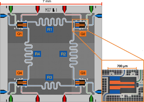
A real multi-qubit chip
.png)
Pulse schedule: what the control electronics play, in nanoseconds
Each qubit on its own, and its readout dots
Q0 readout
Q1 readout
Both qubits together
The chip, sketched
- Reset
- Drive
- Wait
- Readout
- Collapse
- Repeat
Fire a shot to watch each part of the chip do its job.
siliconaluminium, superconductingdrive line + pulsereadout lineJosephson junction
The real thing, zooming in (click a photo to magnify, click again to reset)
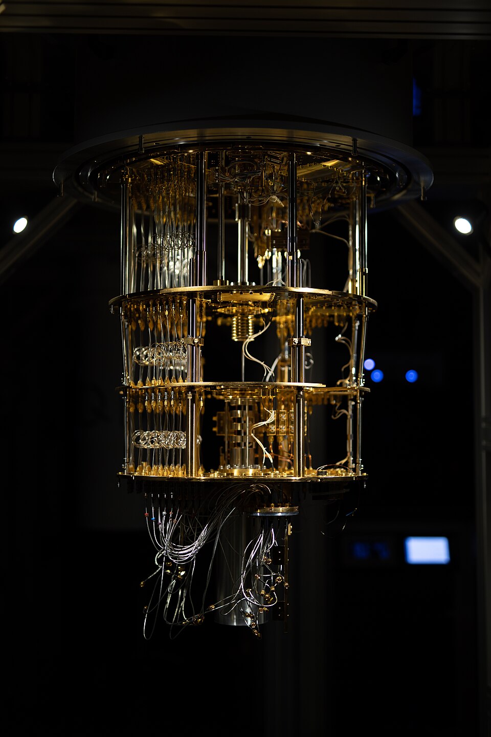 1 · the fridge
 2 · the chip
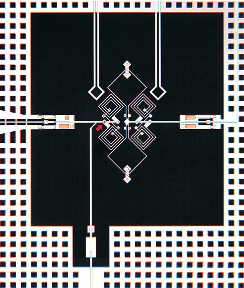 3 · one qubit
.jpg)
The qubit's state
Readout: one dot per shot
Rabi oscillation: P(1) against pulse length
predictedmeasured on the chipfitted curveclick the chart to set the pulse length
Walk through a real lab (videos open on YouTube)
Step inside the Google Quantum AI labGoogle Quantum AI · 2024The Santa Barbara lab: fridges, wiring and the chips inside.
Take a tour of Google's Quantum AI LabGoogle Quantum AI · 2023Research scientist Dripto Debroy walks through the campus for World Quantum Day.
Lab Tour: How IBM tests quantum processorsIBM ResearchJerry Chow and Daniela Bogorin in the lab that checks qubit frequency, coherence and coupler tuning before a chip ships.
Tour a Quantum Lab with Dr. Olivia LanesQiskit (IBM)Where the qubits sit inside a 15 mK cryostat, and the room-temperature electronics that drive them.
Each qubit on its own (Bloch sphere, drag to turn)
Search: rounds of oracle + diffuser
The whole state: one clock per outcome
Disc size is the amplitude (its area is the probability). The blue hand is the phase: right is +, left is −. Outcomes are written |q0…q0⟩.
Measure
predicted probabilitymeasured share of shots